Research
Overview
Simulating multiphase turbulent flows is applicable to a wide range of engineering applications and is a design, verification, and testing tool. However, there exists limitations due to current numerical methods. The goal of this research is to improve numerical methods for the simulation of turbulent multiphase flows so that accurate results can be obtained.
Discontinuous Galerkin Level-set Method
This project developed from an effort to improve the method of capturing the interface location between two fluids in a simulation. In this scheme the quadrature-free discontinuous Galerkin (DG) method is applied to the level-set equations. The DG method and the level-set scheme are described below.
DG is a class of numerical methods such as the more commonly known classes finite difference and finite volume, and DG combines many of the desirable attributes of these other classes. The idea of DG is to represent a function of interest on a set of discontinuous basis functions (e.g. Legendre Polynomials), this allows for an arbitrarily high order approximation of a function. The function is then evolved using appropriate equations. The evolution equations will involve volume and surface integrals which are typically evaluated using quadrature points. A quadrature-free implementation of DG is one in which all integrals are precomputed to save computational cost.
The level-set is one method used to capture the interface between two fluids when simulating multiphase flows. The function is defined such that it is positive in one fluid and negative in the other, locating the interface at the zero isosurface. The level-set is transported using DG applied to a material transport equation. When the level-set is transported, the gradient at the interface can become excessively large or small making it difficult to calculate the interface normal or identify the interface location. When this happens the level-set is reinitialized. Reinitialization is performed by applying DG to a equation that forces the level-set to the desire shape without moving the interface location.
Superb results have been obtained with the transport of the level-set as shown by the figures of Zalesak's disk below. The first figure shows results obtained on a 50x50 mesh, the second used a 100x100 mesh. The order of the approximation is varied and shown as Red=2, Green=3, Blue=4. Work is currently being done on the reinitialization and preliminary results are positive.
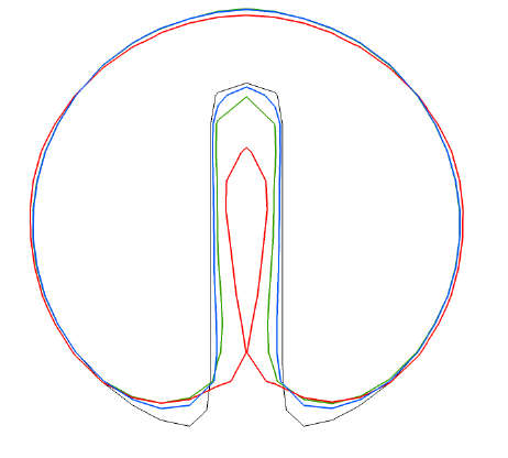 |
| Zalesak disk after 50 rotations on a 50x50 mesh with varying orders of DG approximations (Red=2, Green=3, Blue=4) |
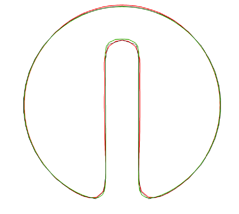 |
| Zalesak disk after 50 rotations on a 100x100 mesh with varying orders of DG approximations (Red=2, Green=3, Blue=4) |
This project involved determining the effects of transverse oscillations on turbulent pipe flow. Transverse oscillations or vibrations arise in a large number of applications including Coriolis meters that measure mass flow rate using the effects of oscillations. Understanding how the oscillations change the flow within the pipe will allow for improvements in Coriolis meter designs.
To simulate an oscillating pipe source terms were added to the discrete form of the Navier-Stokes equations. The source terms accounted for the tangential, centrifugal, and Coriolis forces. After the source terms were implemented a parametric study was conducted to determine how oscillations change the flow. It was found that when the oscillation is around the pipes central axis significant reductions in axial drag were found. When the oscillation is around an axis parallel but not coincident with the centerline, the drag reductions relax and eventually return to the drag found for the stationary pipe.
This research project was conducted at Clarkson University in fulfillment of my honors thesis. I spend about a year and a half working with Prof. Visser on developing and testing a new type of wind turbine know as the contra-rotating vertical axis wind turbine. Unlike more conventional turbines that rotate around a horizontal axis, this turbine rotates around a vertical axis. Additionally it has two rotors that spin on opposing directions. The video below shows the turbine operating in Clarkson's wind tunnel test facility. It was found that having contra rotating rotors allows the turbine to produce more power than a similar turbine with two rotors that spin in the same direction.